LOUGHOR VIADUCT

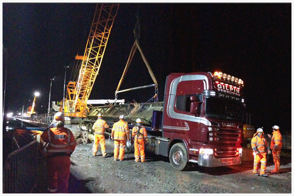
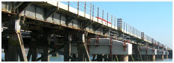
As part of the redoubling works to the South Wales Main Line between Dyffryn and Cockett, the existing 225m long Loughor viaduct had to be replaced with a new structure designed to modern standards. Carillion carried out the works on behalf of Network Rail, and Sam Gilpin Demolition were appointed to undertake the demolition of the existing viaduct. The demolition of the existing viaduct and installation of the new had to be completed within a 249 hour possession, with just 100 hours for the demolition works.

The structure was located in an environmentally sensitive area over the fast flowing Loughor Estuary in South Wales. The structure consisted of 16 spans of approximately 40ft; with the approach spans at each end approximately 50ft. Each span consists of 4 plate girders, with a central RSJ, and cantilevering supports each side. The superstructure is supported by timber piers (the original being designed by Isambard Kingdom Brunel) with the approach spans supported on concrete bearing shelves. The viaduct was originally constructed in timber during the 1850’s and replaced with a steel structure in 1909. The structure was in a poor condition throughout with significant loss of section and significant rot to timber deck

Andun were appointed by Gilpin to produce the F002/03 submission for the demolition works. The package included:

  • Pre-demolition inspection of the structure with verification against Network rail inspection;
  • Working in partnership with Gilpin to select the correct methodology and sequence for the works based on assessed capacity;
  • Design of track protection/working platform for 90 Tonne crawler cranes;
  • Analysis of existing structure to demonstrate that: Proposed plant loadings were acceptable;
  • Lateral and longitudinal stability of the structure could be maintained during demolition;
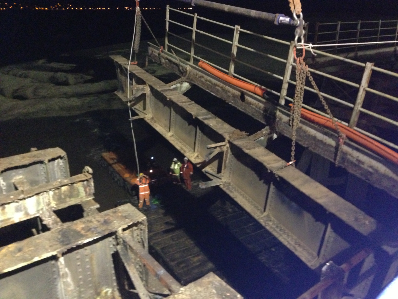
  • Cutting sequence for works, with due consideration of the local stability of the sections;
  • Temporary restraints where necessary to ensure stability;
  • Outline lift planning;
  • Production of 3D sequence drawing illustrating the complete works;
  • Methodology for removing the temporary crossheads supporting the new bridge in the temporary position.

To further complicate the project, the replacement viaduct had been constructed alongside the original on a series of temporary supports. The bridge was to be slid into position following the demolition works; however, the critical path for the work was installing the new abutments for the bridge. To facilitate the installation of the new abutments the end bays of the bridge original viaduct had to be removed first, thereby leaving a potentially unstable structure without any longitudinal restraint. This required careful consideration to demonstrate that there was no danger of the structure collapsing during the demolition works. A temporary restraint system was detailed to mitigate this hazard.

The demolition works were undertaken in the following manner:

  • A working platform was constructed on the new viaduct;
  • The rail, sleepers, ballast and timber deck were removed by 20 tonne excavators working on the original viaduct loading the waste onto dumpers running on the new viaduct;
  • 3 No. teams were brought onto the bridge, one at each end and on in the centre. Each team consisted of a 90 tonne crawler crane, a spider crane and a bridge inspection MEWP.
  • Each team worked independently to progressively deconstruct the viaduct.
  • Each span was burnt into 4 sections and lifted out. The outer teams loaded the sections directly onto the back of articulated lorries, while the central team loaded the sections onto barges in the channel below.
  • The sequence was detailed to ensure that the teams maintained a suitable spacing to prevent overloading of the new bridge.