ONE LEADENHALL- TOWER CRANE GRILLAGE DESIGN

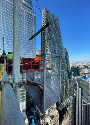
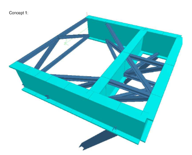
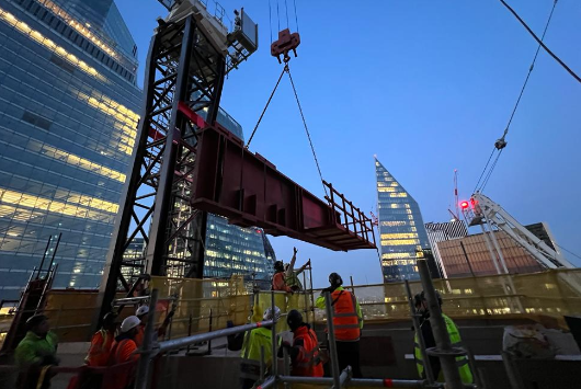
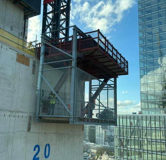
Design of tower crane grillage for an internal climbing tower crane used in the construction of One Leadenhall, a 35-storey structure adjacent to Leadenhall Market in Central London.

Principle Contractor – Multiplex

Crane Supplier – Select/Multiplex Plant & Equipment

Permanent Works Designer – RBG

Fabrication & Installation – Construct-IT

Scope Of Work

At One Leadenhall a pair of internal climbing tower cranes were used in the construction of the structure. 

A grillage was to be installed at level 22, where the profile of the core changed. The Grillage was to cantilever over the edge of the core.

Project Constraints

The initial intent of the permanent works design fixed the position of the crane and the support positions. The remainder of the permanent works also had to be built around our frame, meaning that there was little room to optimise the design beyond the initial intent. 

The main design constraint was the deflection of the grillage. The focus of the design process would be to reduce this, whilst minimising the weight of the structure.

Another constraint was how the grillage was to be installed and facilitating sufficient access for this process.

Design Concepts

The starting point of the design process was to come up with an initial grillage design (see below)

This design was then analysed for deflection and gradual enhancements were made with the impact on the deflection tracked. 

The following changes were considered as part of this process

  • Replacing the bracing beams with plate girders
  • Making the bracing beams larger
  • Increasing the size of the raking member
  • Rotating  the main girder beams
  • Trussing the plate girder

Optimising the angle of the raking prop was also considered but was discounted due to the solution clashing with the permanent works.

Each scenario had deflection calculations made that were exported and compared to find the optimal solution to reduce deflection.

The final design looked as follows

Core Interfaces

There were 4 core interfaces that required consideration within the design:

  • Cast-in anchors for the raking props. These were designed to receive the raking members and had to resist very large tension and shear forces. A combination of weld-on anchors, shear studs and additional rebar within the core were required to resist the loadings.
  • Cast-in tie down brackets. These were designed to clamp the main girder beams down to the structure. The depth of these was dependent on the rebar in the core.
  • Cast-in shear keys. These were designed to resist the lateral forces that were a result of the raking props. These were attached to the base of the beams and sat into pockets within the core’s cover slab. These were grouted into place in-situ.
  • Vertical loading to the top of the core. Local checks were required to ensure that the bearing stress was allowable to the core. Additional bursting steel was added to the core to resist this.

Installation Sequence

The two main girder beams had access frames built on them at ground level. These were then lifted onto the 22nd level and restrained with the Macalloy bars (that were only hand-tight).

The central ‘H frame’ was constructed at ground level, with an internal decking and an access platform to the rear face; this was then lifted into place. Stub overhanging sections were welded to the top of the H section, so that is satit sat onto the edge beams.

A bespoke access platform was then lifted onto the structure to enable access to install the raking props. The raking props were tied down to this platform whilst it was lifted into place.

An extract from the sequence drawings can be found below: