One Leadenhall – Internal Climbing Tower Cranes & Chocking Frames 

Design and sequencing of two internal climbing tower cranes, including chocking frames and associated temporary works used in the construction of One Leadenhall a 35-storey structure adjacent to Leadenhall Market in Central London.

Principal Contractor – Multiplex

Crane Supplier – Select/Multiplex Plant & Equipment

Permanent Works Designer – RBG

Fabrication & Installation – Construct-IT

Scope of Work

The project was to carry out temporary works designs for two internal climbing cranes. Including the chocking frames and climbing beams to be used to enable the cranes to climb through the structures’ lift shafts.

Project Constraints

There were a number of spatial, time and weight constraints that required bespoke engineering solutions to facilitate the installation and climbing of the tower cranes.

Jump form rig 

The cranes had to be constructed within the lift core underneath the jump form rig. Access into the lift shaft was only possible through the lift shaft doors due to the rig operations above.

Time Constraints

The timing and sequencing of the cranes meant they had to be installed, engaged and ready to operate before the jump form rig reached the base of the ballast of the crane to prevent a clash as it got higher.

Core size for crane feet  

The size of the cores differed from the specifications that the cranes were designed for.  

This meant that the standard design for the cranes to use proprietary feet that load the core walls would not work as neither of the cores were the correct size for these cranes.

On Tower Crane 2 (TC2) it was possible to design modifications to the proprietary feet that were signed off by the crane manufacturer, as the width was only marginally out of the cranes specification.

For Tower Crane 1(TC1), Andun designed steel beams that would be fabricated to distribute the load to the core walls. This involved rotating the crane 90 degrees in the core to allow the beams to span outwards across the narrow dimension of the core.

Jack Weights

The design was further constrained by the weight limit of the jacks, meaning that the chocking frames, additional steel beams and trailing decks were constrained to a maximum of approximately 20 tonnes.

Tower Crane One Upper Climbing Legs

A challenge was encountered when considering how to install the upper climbing supports for TC1. Once the jump form rig was in place, there was no access down the lift shaft to lower the beams into position. The solution was to coordinate with Careys, the contractor carrying out the jumpform construction and utilised an additional trailing deck on the jump form rig to lift the beams. 

Once the jump form rig got to the correct level, the beams could be transferred onto the crane. This created an additional trailing deck on the upper climbing beams.

Tolerance of Core Construction

The design had to take into account the tolerance of the core construction, both in terms of its dimensions when installation started and any variations as the cranes climbed up the building.

Permanent Works

The frames needed to transfer the load into the permanent works in a manner which complied with the permanent works concept. Therefore, the loads had to be transferred into the corners of the core where the core had the greatest capacity and had been designed to resist the load.

Design Concepts

The constraints and nature of the project meant that a number of different design concepts were considered before the final design was developed.

Lightweight Climbing Frames and Tension Systems: 

The use of lightweight climbing frames for load transfer during climbing was considered, alongside a system of tension bars tied into cast-in brackets at various levels. This would allow the crane to be tied in and pre-loaded, following each climb prior to operation.

The lightweight frames were proposed to be equipped with rollers to enable easier climbing and adjustment as the crane moved upwards.

The challenge was that the cast-in brackets required for this concept would have clashed with the brackets for the external steelwork in the core. 

This would have necessitated more frequent jumps (movements of the crane), negatively impacting the already constrained programme of the project. The use of a significant number of cast-in brackets was also not a sustainable solution once the number of climbs increased due to clashes.

Design Solution – Compression Frames

The design that was developed was for a series of compression frames that climb with the crane. These frames were designed to be attached to the crane and used to resist horizontal loads and torque loads when the crane is in service.

The proprietary feet for TC2 were modified to directly load the core walls and no additional steelwork was required for the load transfer. 

For TC1, the crane was rotated 90 degrees so the proprietary feet were oriented along the long axis of the core. Plate girders were designed to transfer the loads out to the core walls. 

The feet were designed to rotate on pins so they could be retracted when the crane was climbing.

Chocking Frames

The chocking frames were lightweight frames that were fabricated into panels that were manoeuvred into position, lifted up and then fixed up the crane mast.

There were also corner skids designed to run up the corners of the core walls to transmit the loads. Jacking positions were incorporated that allowed for the tolerance of the core between the skids and the frames. 

These frames transmitted all the horizontal loads from the cranes, both the in-service and torque loads from the crane operating and the out of service loads due to high winds. These frames act as a force couple and resist the imposed moments on the crane. 

Frame Construction

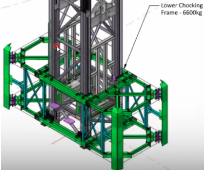
For Tower Cranes 1 and 2, the upper chocking frame was designed to be constructed at basement level, The frame was then hoisted into position, approximately 16m up the crane mast and fixed into position. The lower frame could then be constructed at basement level and fixed to the mast.

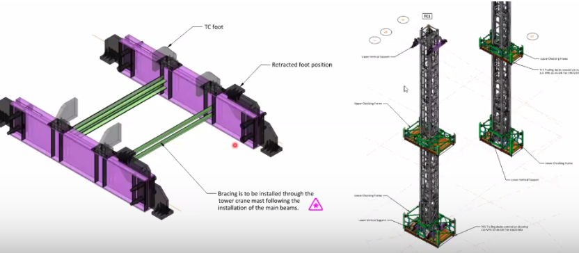
Both frames had a trailing deck to allow access during the climbing process, which was constructed at the same time as the chocking frame.

Following the construction of the frames on TC1, the vertical support beams could then be slotted through the frame and into position.

Jacking Arrangement

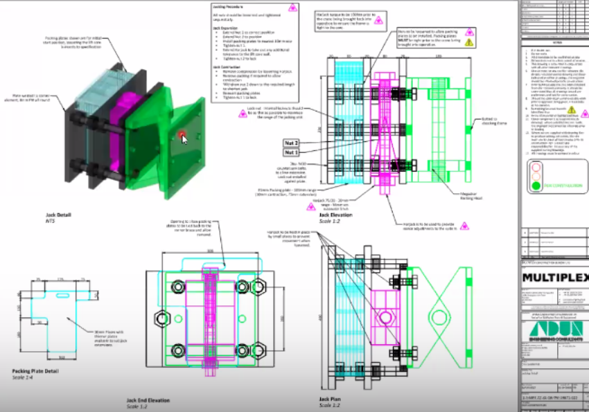
The jacking arrangement was designed using harjacks (wedge jacks) that can provide pre-load, but only has a single mechanical bolt and no hydraulics. This mitigates against the risk of failure and provides an easily inspectable jacking arrangement. 

This robust system was designed to enable micro adjustments to be made during climbing with minimal intervention.

Additional Resources

Chocking Frames, Tower Cranes & Grillages Webinar

Cirria C761 – Guidance on Tower Cranes