Regent Street Flyover – Prestressed and Post-Tensioned Demolition

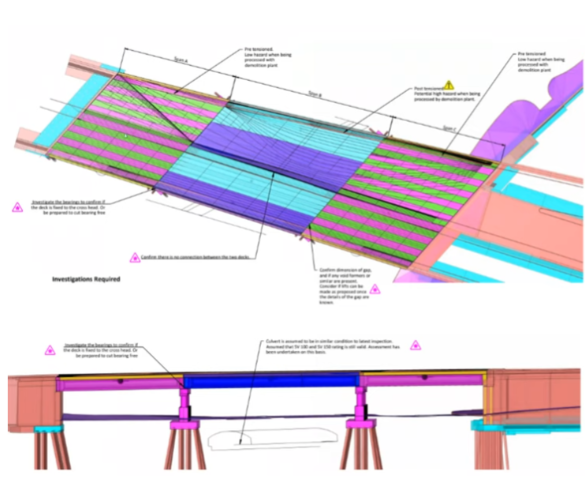
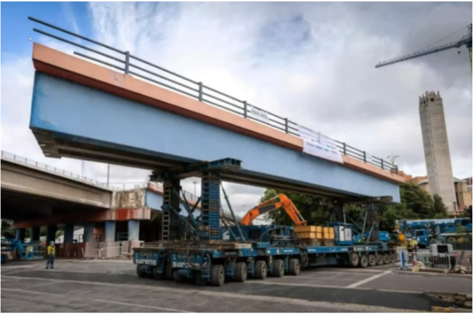
Demolition engineering for removal of a post-tensioned bridge with prestressed elements in central Leeds with a dual carriageway over the top of the structure in both directions and a main road underneath. 

Additional complexity due to the small site footprint and the requirement to retain the original piers and abutments for use on the replacement structure. 

There is also the large masonry sewer underneath.   Clearly shown on drawings, and discussed in webinar

Client: Leeds Council

Contractor: Balfour Beatty

Demolition contractor: Sam Evans and Sons

SPMT and Lifting Contractor: Sarens

Scope of Work

The structure is of 3 spans. The central span being post tensioned, while the outer spans were pre-tensioned. The beams were supported on RC abutments and piers.  

The client required a demolition methodology that retained the existing reinforced concrete piers and abutments for use on the new bridge. 

Constraints

Reuse of concrete piers and abutments

The requirement to retain the piers and abutments for the new bridge was a considerable constraint as it reduced potential demolition methodology options as percussive methods to demolish the structure in situ could not be considered.

Site Footprint

The location with the A64M dual carriageway above and the A61 road bridge below combined with the small site footprint created access challenges.The site constraints meant that there was a limit to the size of the SPMTs used to lift and transport the bridge beams.

Demolition Methodology

The bridge was demolished in two phases to allow the replacement bridge to be built at the same time. The prestressed outer spans were demolished first. These were removed by maintaining approximately the same point of support as their as-built condition. 

This meant that the bending forces in the beams did not change significantly from their designed loads which made the justification easier compared to the post tensioned beams in the second phase. 

To demolish the post tensioned beams ideally the methodology would have lifted the bridge to match the existing conditions by supporting the bridge in positions to match the existing load path.

As this was not possible it resulted in reversal of the bending loads, the solution was to study and understand how the original structure was built. The structure was cast insitu, then post-tensioned. The deck was then cast insitu.   As the beams were lifted up onto the bridge bearings into place and the bridge decks cast in situ. 

This means that the deck only picks up loadings due to the application of live load to the deck. It also means:

  1. The slab is not in compression under dead load only;
  2. The post-tensioning forces are resolved within the beam itself. This means compressive loads due to the tendons only put the beams cross section into compression, similarly moments due to the tendons are resolved within the cross-section of the beam. 

This means that the reinforcement in the deck can be utilised to resist the hogging moments generated by the change in support condition. 

Lifting Constraints

The central spans were driven out using SPMTs

The lifting contractor Sarens conducted analysis and modeling to determine viable SPMT options, given site access constraints. This included testing different SPMT configurations and “swept paths” to model manoeuvrability.