01245 360 194

Demolition engineering and associated temporary works design of two flyovers in central Liverpool. A highly complex project with a large number of engineering design challenges and environmental constraints.
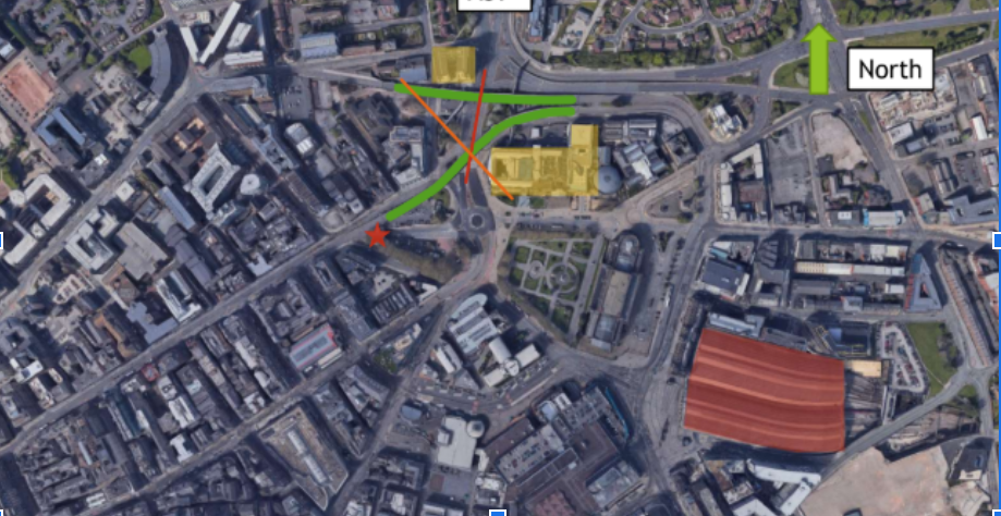
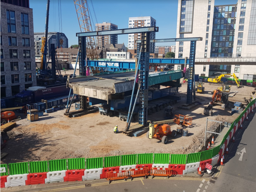
The Churchill Way flyovers were a pair of dual carriageway flyovers that connected Lime Street to Dale Street and Tithebarn Street in central Liverpool. They opened in 1970 and were designed to form part of the city’s cancelled inner ring road scheme.
The flyovers were closed in September 2018 due to structural issues related to the post-tensioning and the decision was made to demolish them.
PROJECT TEAM
This complex scheme required a demolition sequence that could only be achieved through high levels of collaboration between the stakeholders and contractors commissioned by Liverpool City Council.
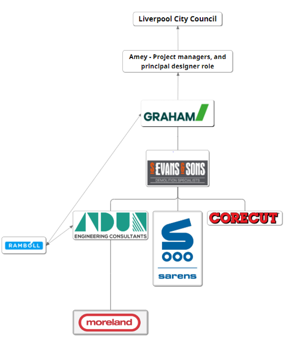
The main team comprised of the following companies
Liverpool City Council – Client
Graham– Principal contractor
S Evans & Sons – Demolition contractor
Andun Engineering Consultants – Demolition engineering and lead temporary works designer
Sarens – Lifting equipment and SPMTs
Corecut – Concrete cutting equipment
Ramboll – Cat 3 Checker (Structures)
Moreland Consulting Engineers – Cat 3 Checker (Temporary Works)
LOCATION CHALLENGES
The inner-city location of the flyovers and the small site area meant that the demolition sequence had to be highly choreographed to overcome the logistical challenges that this created.
There was limited space around the structures in which to operate. Further complicated by the presence of statues and trees containing nesting birds that could not be removed.
The position of the structures meant that road closures would be required, which created logistical and timescale challenges due to the need to minimise closures.
There was also the need to maintain pedestrian flows through the area.
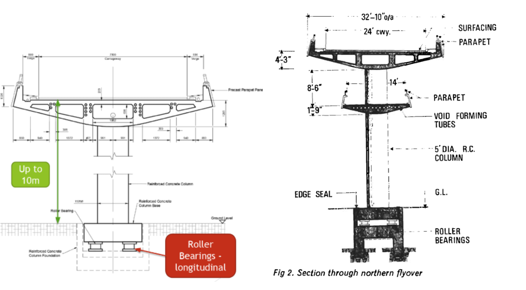
THE STRUCTURE
Each of the flyovers were continuous post-tensioned structures over 240m long. Individual span lengths varied from 14m to 33m.
There was one fixed central bearing at the centre of each structure and longitudinal bearings on the other piers, allowing the flyovers to expand and contract with the temperature variation.
POST TENSIONING
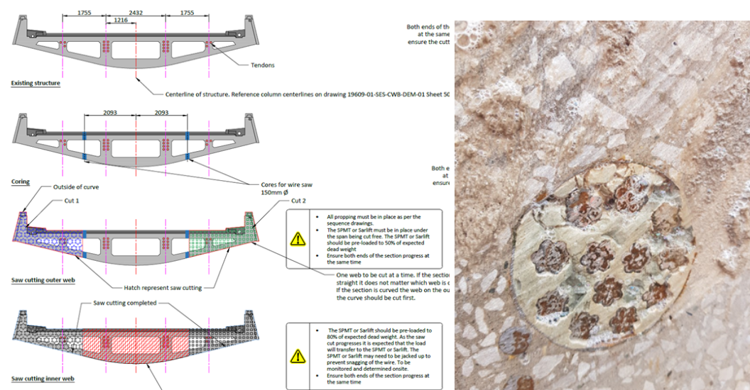
As the structure was post-tensioned it was necessary to confirm if the tendons were bonded or not bonded. In simple terms this means, will the tendons re-anchor, or will they release the tensile forces when they are cut.
Checks of the grouting surrounding the tendons at numerous points throughout the structure confirmed that the tendons could be considered bonded. The checks were undertaken at the high and low points of the tendon profile to ensure they were bonded throughout.
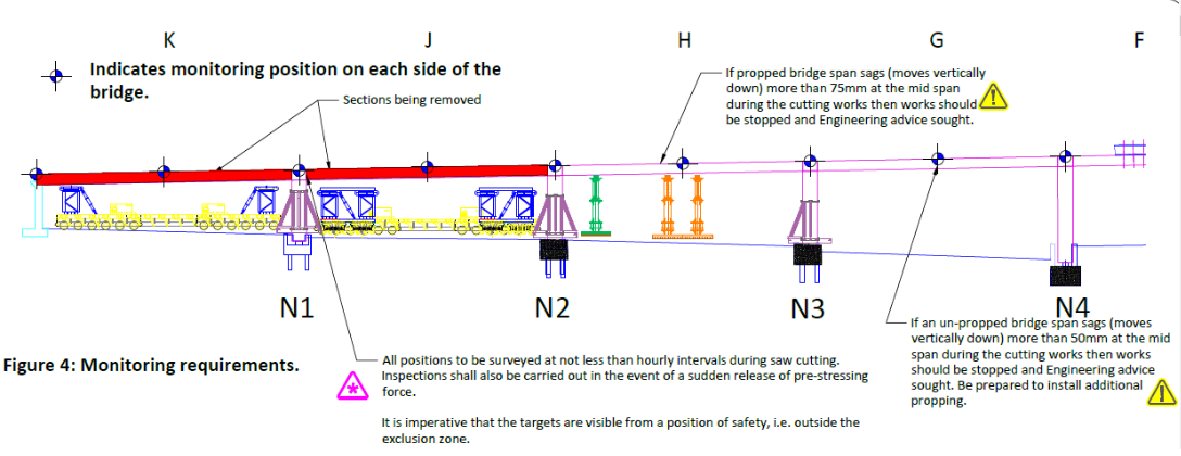
FAILSAFE PROPPING
The first spans to be removed were K and J. The assumption was that when the tendons were cut they would re-anchor, as such the adjacent spans would not be destabilised by the works. However a risk assessment, identified that there were two potential failure mechanisms that should be mitigated, these were as follows:
- Shear failure
The re-anchorage length required for a tendon can be significant. The reduction in compressive forces (due to post-tensioning) can significantly reduce the shear capacity of a section. In this case, the distance between the proposed cut line, and the point of high shear on the adjacent span was around 1.5m, which is below the maximum theoretical re-anchorage length calculated. As such, there was potential for a shear failure to occur. A prop was designed to support the weight of the bridge in this worst-case scenario.
2. Bending failure
Similarly, if the anchorages failed then the bending capacity of the span is significantly reduced. Therefore a propping solution had to be developed to carry the span should this failure occur.
Due to the magnitude of the loads potentially needing to be supported, proprietary props were not suitable. The footprint and shape of the propping was significantly affected by the need to drive the SPMT’s into position, as such the props were designed specifically for the scheme.
The props have been designed in modular sections to allow Sam Evans & Sons to reuse the props on future demolition schemes. The capacity and height versatility of the propping structure means there are not many projects where these props could not be adapted to provide a solution.
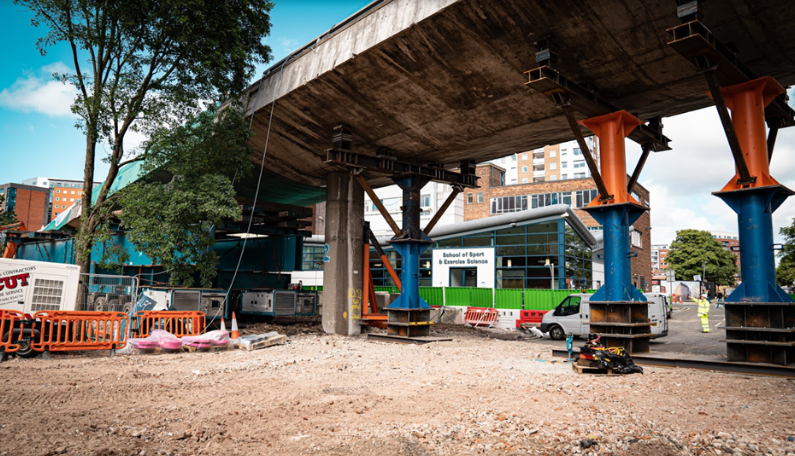
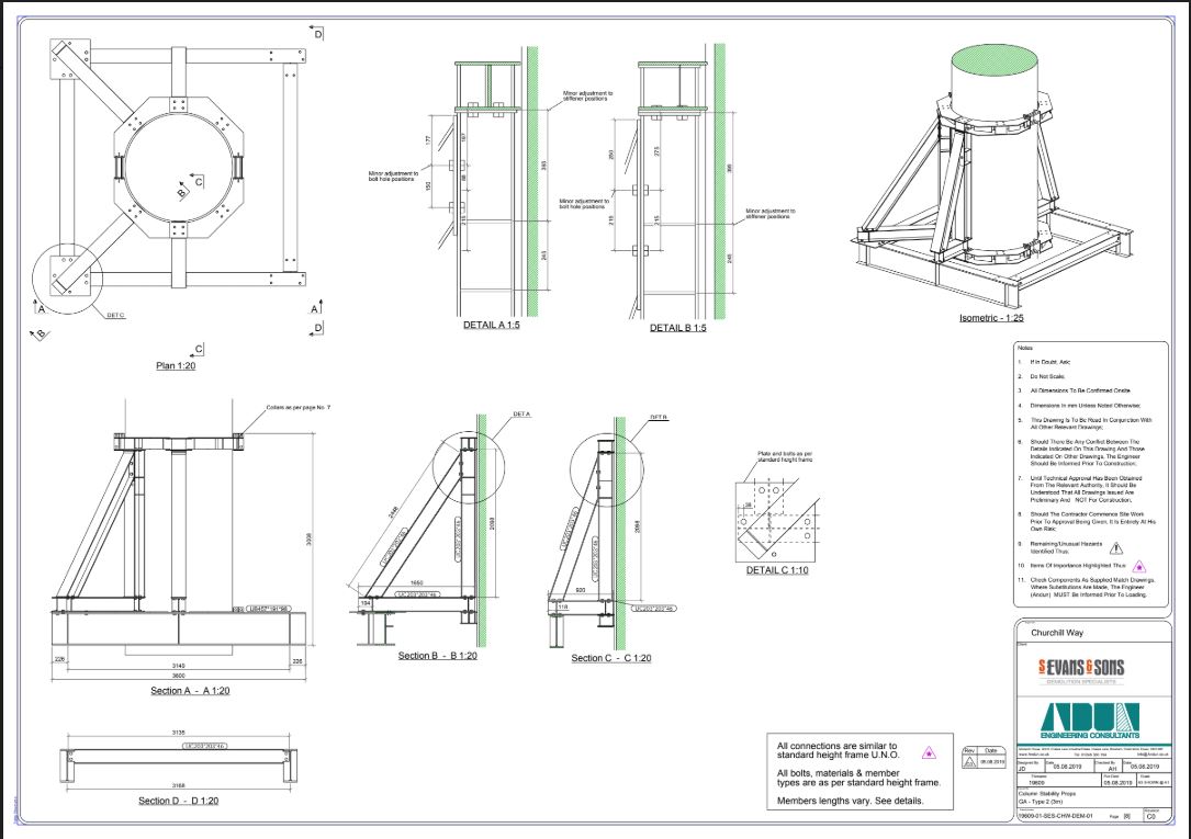
COLUMN PROPPING
Due to the sequencing, it was necessary to prop the columns to add stability when the first spans had been removed, particularly given the potential for movement as the piers are sitting on longitudinal bearings.
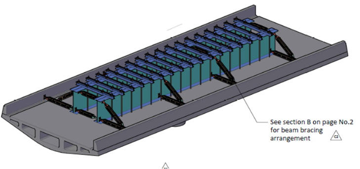
SPANS NE AND NF
Initially span NE & NF were to be removed as individual units, in a similar fashion to adjacent spans, however, the initial SPMT stability analysis indicated they would not be stable.
Therefore we proposed to take both spans out as one unit.
To achieve this two steel beams recovered from a previous Sam Evans & Sons project were placed on top of the structure. A series of rapid tie anchors were used to strap the deck unit to the beams, thereby allowing both spans to be removed as one.
SAW CUTTING AND TENDON RELEASE
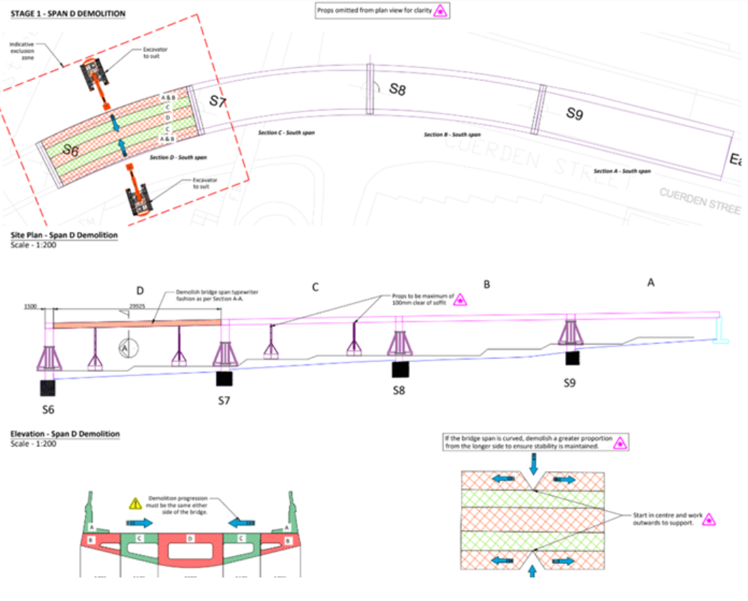
The saw cutting and the release of the tendons needed to be carefully planned. When releasing the tendons on the curved sections of the deck, it was important to do the outside cut first, then the inside cut and finally the mid section.
The SPMTs were jacked with 80% dead load to prevent sagging as the cuts were made.
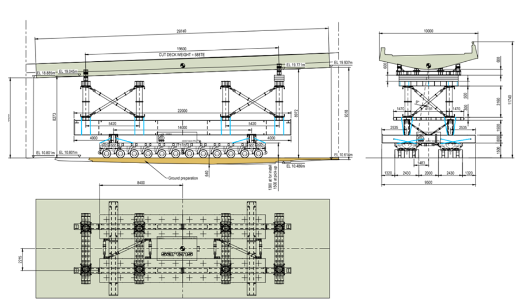
SPMT AND HEADER BEAMS
The shape, slope and height of the structure and surrounding areas created a challenge to ensure that the SPMT could drive underneath the structure and lift it up with a stroke of only 600mm.
An additional challenge was the stability and slope of the site when traversing 650-tonne sections of concrete around.
Every move of the SPMTs had to be carefully planned to ensure that there was a suitable route in place, with planned levels, cross falls and gradients to suit.
SAR LIFT
A SAR lift 2500 was used to remove the sections from the SPMTs. The SAR lift, raise the span and the SPMT drives away, the sections were then lowered onto a designed steel grillage. Again, a specific grillage had to be designed given the shape and weight of the sections in question. A series of steel beams from a Sam Evans & SOns site were used to form the grillages.
TRADITIONAL DEMOLITION FOR THE LAST FOUR SPANS
The last four spans of each flyover could be removed using traditional demolition methods. This meant starting at one end and working back to the abutment breaking the spans down and working along the structure.
Propping was used due to the long span lengths, allowing the sections to sag and sit down onto the third point props as the works progressed.
DESIGN OUTPUT
- AIP submission for Structural assessment of structure- Cat 3 checked and validated by Ramboll;
- AIP submission for temporary works design. To Eurocodes. – Cat 3 checked by Moreland Consulting Engineers;
- Full 3d sequence drawings for the scheme. Including make up for each individual prop position;
- Design of all working platforms. Including individual platform designed to meet the tight movement criteria for the SPMT’s;
- Design of all temporary works, with full fabrication drawings for all components;
- Lead designer role as per BS 5975:2019. Andun were responsible for reviewing and coordinating the Sarens designs with the overall package;
- Weight estimates;
- Working platforms for SPMT’s, 500te mobile crane, 400te crawler crane, Sar Lifts and grillages.
- Mechanical demolition proposal for 8 spans;
More than 200 drawings, 30 sets of calculations, 2 AIP’s, DRA’s and numerous meetings. All delivered in a 3-month time frame.
PROJECT OUTCOME
This was a complex and challenging demolition project that required significant effort and collaboration from the different parties involved. It was completed safely, on time and on budget.
Churchill Flyovers In The Press – https://www.liverpoolecho.co.uk/news/liverpool-news/striking-images-show-how-liverpool-17161703