Mytholmroyd – Bridge Demolition & Replacement

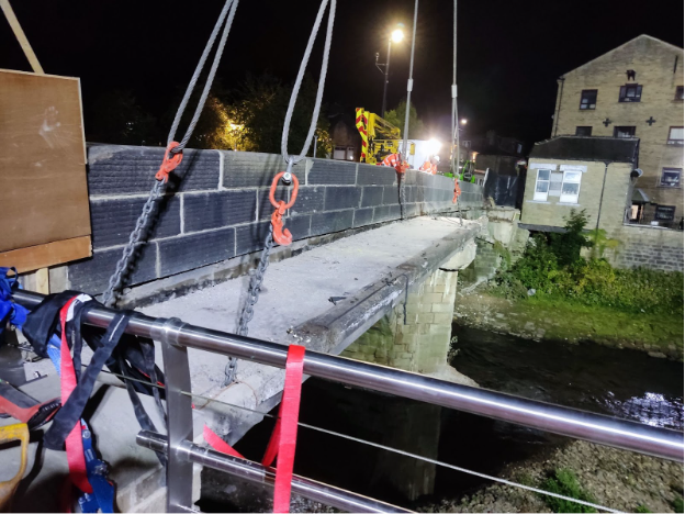
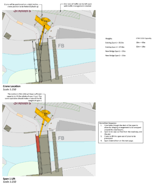
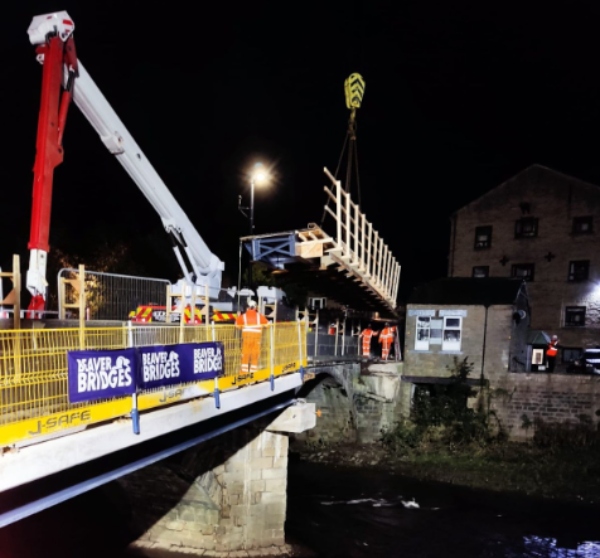
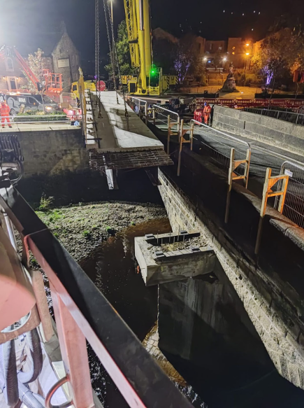
Replacement of a two-span footbridge over the River Calder in Yorkshire with significant constraints during the demolition and replacement installation phases.

Project Scope

Andun Engineering Consultants were involved from the initial concept stages of the project with the brief to design the demolition engineering of an existing footbridge and the installation of the replacement bridge. 

The constraints on this project transformed this from a relatively straightforward project into a complex project requiring innovative engineering solutions.

Project Constraints

The following constraints and how they impacted the engineering decisions will be discussed throughout the case study.

Limited crane capacity – The council stipulated that a 450Te crane could not be used, adding complexity to the demolition and replacement installation phases. 

Environmental considerations – the brief stipulated that no debris or fines could be allowed to runoff into the river 

Flooding risk – the fast-flowing river below is a well established flooding risk with significant risk of flash flooding. This meant that no materials or plant could be placed on the riverbed during either phase of the project. The channel could flood in < 5 minutes. 

Poor permanent works design – The original permanent works designs for the replacement bridge installation added significant risk to the project, and the second span was unbuildable as planned by the permanent works engineer.

Demolition Phase

The initial concepts for the demolition phase of the project was to use a 450Te crane that would have allowed the two spans to have been lifted out in one piece and then processed. 

This constraint limited the scheme to a 250Te crane that did not have the lift capacity to take out the second span in one piece. 

Span One

The first span was lifted out in one piece as per our initial design concept.

Span 2

The solution was to instead cut the span into smaller sections to accommodate the lifting capacity of the smaller crane. The challenge was to allow the bridge to be pre-cut and then all panels lifted out in one night time partial road closure. We overcame this by providing a designed sequence as shown on the drawings below. 

Before the saw cutting started, an aluminum sheet was put across the underside and secured with fixings underneath the span to capture the saw cuttings and any runoff.  

Construction Phase

Andun Engineering Consultants were also involved in the engineering for the installation of the replacement bridge. 

The permanent works designer created significant challenges for the construction of the bridge. They had specified an in-situ construction methodology that required propping to be founded on the river bed. 

This, combined with the crane size restraint, meant innovative approaches and engineering solutions were required for the construction of each of the spans.

Span One

The initial permanent works design was for both spans to be built in situ. This would have increased the risk of the project due the requirement to have people working at height over a fast moving river. 

Instead span one was constructed off site with edge protection and lifted into place by the 250Te crane, as shown below. 

Span Two

The second span had to be built in situ over the river due to the size of the crane for the project. 

The initial permanent works design was not a suitable construction methodology, as the beam designed was not capable of supporting the concrete in its wet condition without propping. The outline construction sequence had a prop set into the river to support the beam. 

Under CDM regulations, the PW designer had a responsibility to remove this hazard but this did not occur and an alternative construction methodology was required.

The first step was designing additional bracing for the bridge so that it could support the wet weight of the concrete. 

Then a formwork system was designed, which could be installed and removed within the constraints of the site, so that no propping or structure that restricted the headroom of the river was required. 

In situ permanent formwork was designed to sit on ribs that pick up permanent formwork. Metal brackets hung off the edge of the girders allowed the formwork to be built on the edge to pick up the form of the concrete and provide edge protection. 

These engineering solutions transformed the project to one that could not be built to one that was able to be installed successfully by the bridge contractor.